THE PHYSICS OF FOUNDATION BRAKES
HEAVY TRUCK BRAKING & AIR DISC BRAKES 2 : 1 4
To have a full appreciation of the evolution of foundation brakes, we must first understand their physics.
A fundamental rule of physics, the Law of Conservation of Energy, asserts that the total amount of energy in the universe remains constant over time. A corollary to this law is that energy can neither be created nor destroyed; it can only be transformed from one state to another. This fundamental rule also applies to heavy truck engines and brake systems. In the case of the diesel engine, the potential energy – energy stored in a body – is the diesel stored in the fuel tank. This potential energy is converted to kinetic energy – energy associated with motion – by the engine and drive train. While the drive train’s key role is to move the vehicle, it is the primary responsibility of the braking system to bring it to a stop.
In this equation, KE is kinetic energy, M is mass or load, and V is velocity or speed.
When considering this equation, two things are clear: (1) the impact of vehicle weight on braking demand is significant, but linear; and (2) the impact of speed on brake demand is exponential. When factoring in the Law of Conservation of Energy, the kinetic energy of the moving vehicle must somehow be transformed as the vehicle slows and eventually stops. In the case of the braking system, this energy is transferred into work and heat. The brake systems’ ability to generate the required torque to slow the vehicle, and then dissipate this heat into the atmosphere, becomes the most important aspect of any vehicle braking system.
In the bathtub illustration, the amount of water the tub can hold is its capacity. In the case of the braking system, thermal capacity is largely dependent upon the size, shape, and material of the drum or rotor. Drum and rotor materials are primarily made of cast iron, an economic material that provides the needed thermal capacity. Lighterweight drum designs use less cast iron – or a combination of iron and steel – to achieve reduced weight. Unfortunately, this weight reduction comes at the expense of the system’s thermal capacity.
Continuing with the bathtub analogy, the rate at which water is added to the tub by the faucet is similar to the rate at which the braking system adds heat to its capacity as it transforms energy into heat during active braking. As the brakes are applied, the temperature increases.
In this example, as water continues to fill the tub, the drain simultaneously removes water, preventing it from overflowing. In a steady-state condition, the tub must drain faster than the faucet adds water. The function of the drain is similar to the brake system’s objective to dissipate heat. An example of how this analogy applies to the braking system is illustrated in sustained downhill braking. In this situation, the brakes are used constantly, adding heat to the system over a sustained period of time without the luxury of a complete cool down.
Going back, once again, to the bathtub illustration, we analyze what will happen if the drain is unable to keep pace with the rate at which water is being added. In this scenario, the tub will overflow. Overflowing water means that the capacity of the system has been exceeded. This is parallel to the braking phenomena known as fade. Fade is the condition in which the thermal capacity of the braking system has been exceeded and the system operates at reduced effectiveness.
Heat Dissipation and Thermal Capacity
As the brake system converts energy into heat, two factors become important: (1) the amount of heat the system can retain – commonly referred to as thermal capacity; and (2) the rate at which it releases that heat into the atmosphere, known as the heat dissipation rate. To illustrate this point, we can use the analogy of a common bathtub.
The most common type of foundation drum brake is the S-Cam
Brake, commonly referred to simply as Cam – or Drum – Brakes. Cam Brakes are actuated by applying input force from an air chamber or actuator. This force acts against a lever arm, which doubles as a slack adjuster to turn the camshaft.
The head of the camshaft actuates both brakes’ shoes and resembles the letter “S.” It is this feature that gives the S-Cam Brake its name. Because of their simple design, relatively light weight, and economic cost, S-Cam Brakes are currently used on approximately 95 percent of all North American Class 5-8 air-braked vehicles.
Since 1995, all air-brake equipped vehicles in the United States and in Canada have been required to use automatic slack adjusters, commonly referred to as ASAs or simply “slack adjusters.”
The ASA keeps the brake in constant adjustment by advancing the camshaft forward as the friction material wears. As the slack moves to and from its reference point, it advances its position as the specified brake application stroke is exceeded. This helps the vehicle maintain a reasonable brake stroke as the brake lining wears. The ASA is integrated into the brake lever and is generally mounted toward the inboard side of the chassis, along with the air chamber and parking brake.
Wedge Brakes
Although no longer common in North American applications, the other major drum brake design is the Wedge Brake.
There are two types of Wedge Brakes:
Simplex (single actuation) and Duplex
(dual actuation). With greater complexity, cost, and relatively high hysteresis (release responsiveness), Wedge Brakes have been relegated to specialty and niche applications where their robust sealing, compact packaging, and durability warrant the added weight and cost. Unlike the S-Cam Brake, the Wedge Brake’s adjusting mechanism is incorporated into the housing of the brake itself.
As a result of their design, all drum brakes – S-Cam and Wedge – incorporate a varying internal amplification, which is expressed by the brake factor “C*.” This parameter defines the relationship between the brake’s braking (output) force and actuating (input) force. The brake factor “C” is determined by the friction coefficient of the friction material used and the mechanical advantage of the brake design. Because the friction coefficient, brake stroke, lining, and drum condition can all vary slightly between wheel-ends, the variation is amplified by the mechanical advantage of the brake design.
This factor results in a greater sensitivity to variation in drum brakes. The heightened sensitivity can result in moderate levels of torque output variation between like brakes on either side of the axle. These phenomena – coupled with its susceptibility to fade – represent the general shortcomings of drum brakes.
Air Disc Brakes – often referred to as ADBs or disc brakes – offer an alternative to drum brake designs. When compared to drum brakes, air disc brakes have a number of advantages, including:
• No exaggeration of friction coefficient differences: This results in improved side-to-side consistency between left and right brakes.
• Reduced fade: Consistent contact between the friction surfaces remains, even with brake disc warm-up and radial expansion.
• High thermal load: Heat dissipation is efficient for internally vented brakediscs. As such, it is possible to maintain high braking performance, even in demanding conditions.
• Minimal and consistent hysteresis: This is due to the high efficiency of the actuating mechanism.
• Servicing ease when changing brake pads: When compared to drum brakes, disc brakes require only a fraction of the service time.
These advantages – coupled with an increasing demand for higher performance, safety, and less frequent maintenance – have resulted in the growing acceptance of conventional air disc brake designs.
Early Air Disc Brake Designs
Air disc brakes have been used on North American air-braked vehicles since the early 1980s. Early designs were actuated by either a single power screw or a wedge.
Although relatively lightweight and economical, these initial designs were used primarily in heavy trucks and specialty vehicles. While greeted enthusiastically by fleets and end users that desired the improved performance and safety they could deliver, early air disc brake designs were plagued by a number of design shortcomings, as well as difficulties with maintenance and service.
Design Shortcomings of Early Air Disc Brakes Initial air disc brakes were earmarked by a number of shortcomings in their design, including:
a power screw design that had good apply but poor release characteristics (Hysteresis ~30 percent);
slide pins that were chrome plated and unprotected, making them subject to flaking, corrosion, and seizing;
pads that were attached to the brake caliper, making the caliper subject to clamp load and brake torque;
a single-piston design, which did not provide uniform pad wear; and brake rotors that were undersized (typically 15 inches) and not optimally designed, increasing their potential for cracking.
Early air disc brake designs featuring
Maintenance and Service Challenges of Early Air Disc Brakes
The first air disc brake designs also came with inherent maintenance and service challenges, including:
• designs that were not sealed, meaning they required regular lubrication;
• pad changes that were both time consuming and difficult, adding substantial cost to overall maintenance expense;
• exposed slide pins that often became corroded, causing caliper seizure and unequal inner-to-outer pad wear; and
• pad-to-rotor clearance that was dependent upon rotor vibration for proper return and clearance.
Leave words, your message replied in 24hours.
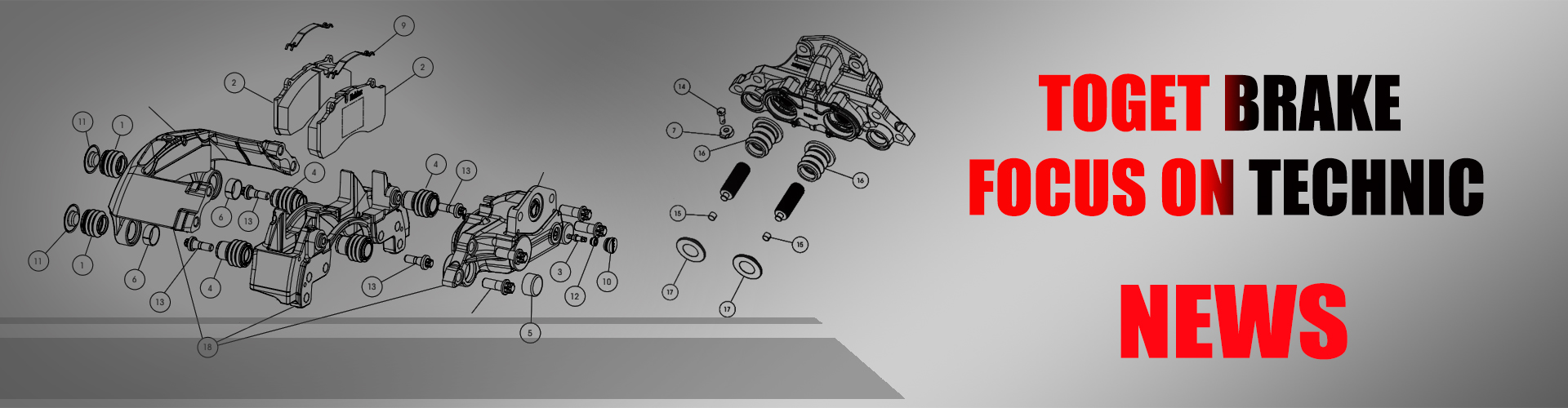
Toget Brake
Brand Vision:"to become the China leading supplier of active vehicle safety systems within the commercial vehicle industry."
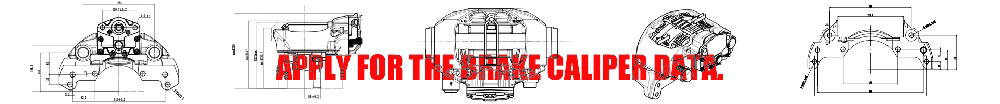
At Toget, focus on air disc brake calipers technics, exceeding industry standards is a strict requirement.
Brand names, original numbers, vehicle mark and models are only for reference purposes.


